Tag Archives: metal

Hammer Time

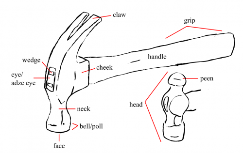
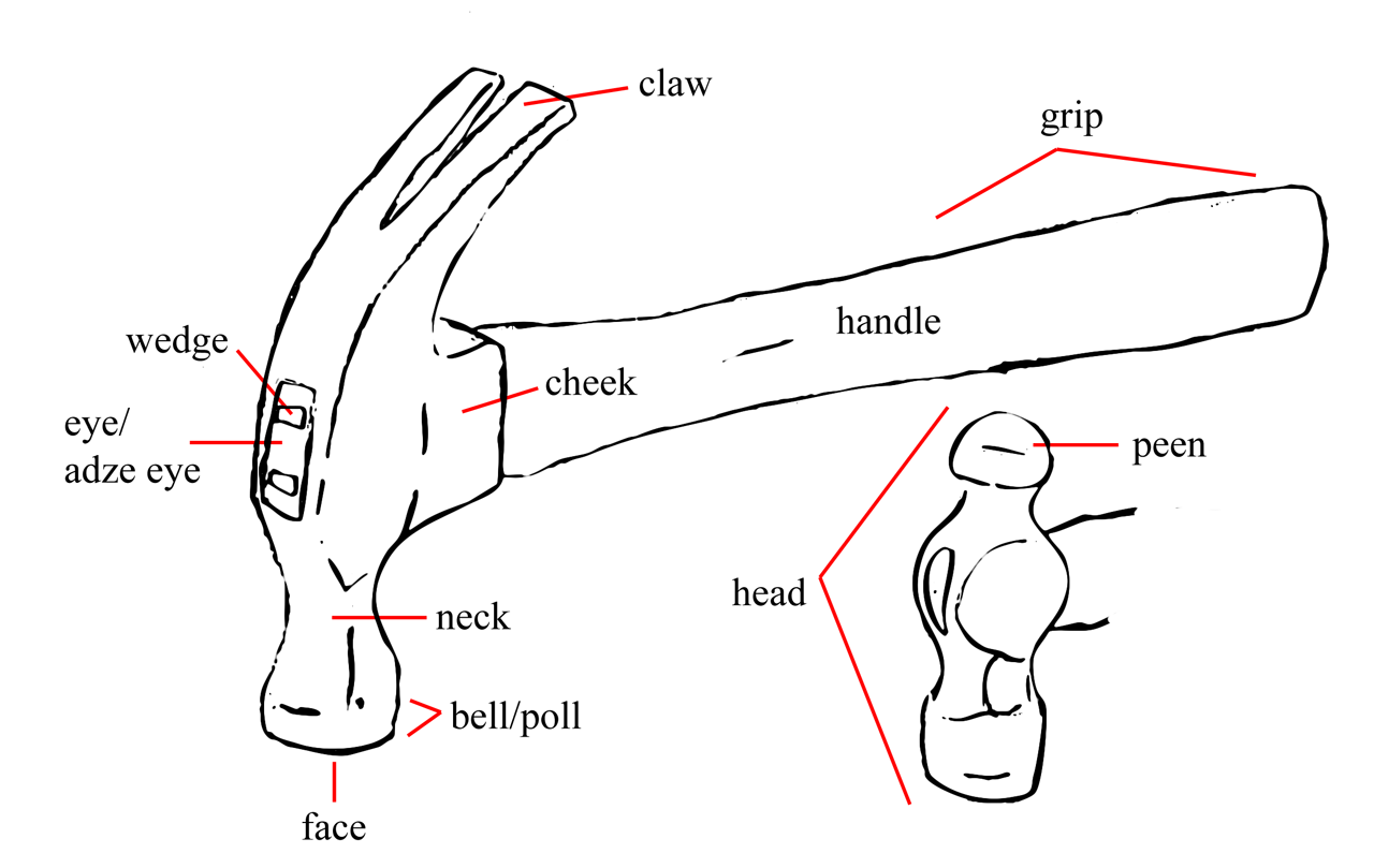
Parts of a hammer
Parts of a hammer

Your basic hammer is made of two parts: the handle and the head. The handle fits through a hole in the head known as the eye (or adze eye), and is held in place with a wedge. On newer hammers, the grip may be wrapped in rubber for greater comfort. The face is what strikes the nail or other surface you are hammering. Hammers used for peening, or shaping metal come in a number of varieties. A ball peen hammer has a peen with a hemisphere shape. A claw hammer has a claw used for removing nails or separating two pieces of wood.
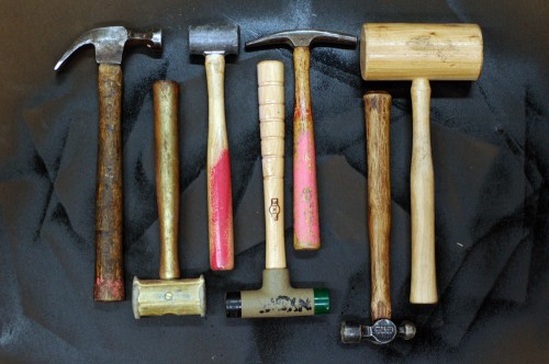
Types of hammers
Types of hammers

I gathered some of the hammers we have in our shop, which represent some of the more common types which are useful to the props artisan. From left to right, we have:

Claw hammer: Your basic carpentry hammer is useful for driving and removing nails into wood. It’s also the go-to-hammer for basic “hitting stuff”; I kind of cringe every time I see someone grab a ball peen hammer to knock something loose.

Rawhide mallet: Useful for non-marring blows, especially when working with leather, jewelery or other softer and delicate metals.

Lead mallet: These are used to hit steel without the risk of creating sparks. You can also get copper mallets for the same purpose.

Soft-faced hammer: The faces are made of soft materials, such as rubber or plastic, and are often removable and replaceable. These are used when you are hammering on or around decorative or finished wood to keep from marring the surface.

Tack hammer: Used in upholstery to drive tacks. One end is split and often magnetic to help hold the tiny tacks while driving them in.

Ball peen hammer: Peen hammers are used for shaping metal. Besides the ball peen, you may also find straight peen, cross peen, and point peen, among others.

Wooden mallet: Or carpenter’s mallet, used for furniture assembly or driving in dowels when non-marring blows are needed.

You can of course find any number of other types of hammers and mallets, with many variations in between. Prop shops will often carry rubber mallets, rip hammers and sledge hammers. Other types of hammers, such as bricklayer hammers or drywall hammers may also find their way into shops. Check out the Science and Engineering Encyclopedia for a comprehensive list of hammers.

Sheet Metal Bending Brake

As I mentioned in my last post, I had to (or rather, wanted to) make a sheet metal bending brake for one of my latest projects. A brake is basically a tool (or jig) in which you can insert a piece of sheet metal, and then make a clean fold or bend in a straight line.

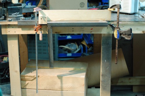
Front view of the brake

Again, I have to credit this post on Dave’s Sheet Metal Bending Brake for getting me up to speed on the best way to design a brake.

Side view of the brake

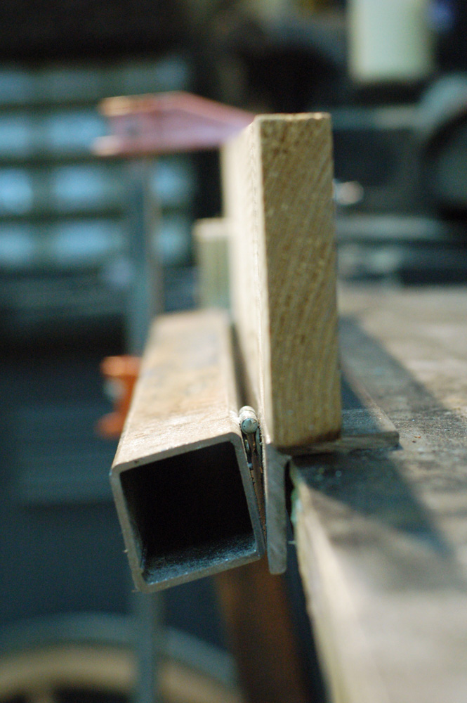
The piece of angle-iron is screwed to the worktable. The square tube is attached to the angle-iron by two small hinges, which are welded on. The tops of the bar stock, hinges and angle-iron are all in line with each other. Finally, I have a piece of wood which can be clamped down to the brake; the front face of the wood is lined up with the front face of the angle iron.

Sequence showing a fold being made

The metal is laid on the box tube and angle iron. The wood is clamped down. The fold will happen at the edge of the wood, so we mark the metal where we want the fold, and line that mark up with the edge of the wood. When you lift the handle, the metal bends with a nice sharp crease.

Here is a brief video of the brake in action making all the folds on one of the footlights.

Art Deco Footlights

A footlight
A footlight

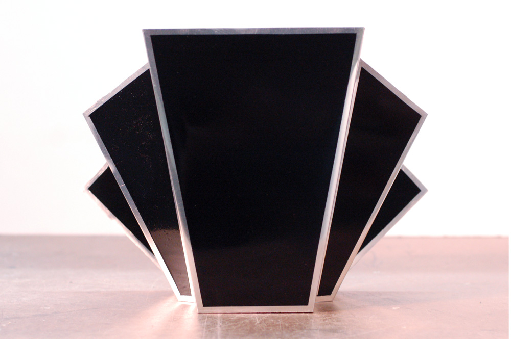
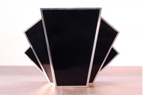
I recently finished up a number of footlights for a company called Punchdrunk for their upcoming New York production of Sleep No More. Their Boston production used traditional shell-shaped footlights; for this update, the stage had a giant art deco backdrop whose shape would be mirrored in the footlights.

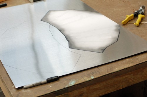
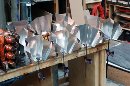
They provided me with a full-scale drawing of the piece with all the angles already figured out. I traced the patterns onto sheets of aluminum. I kept the top edge along the factory edge of the aluminum sheets; with that edge being front and center, I wanted it to be the straightest and cleanest part of the footlight. The first light I cut out using my pair of tin snips. It gave me a clean edge but took forever. I cut the next one out on the bandsaw. It was a lot faster but was harder to keep nice-looking. I ended up using both of the tools to cut, with the bandsaw cutting out the rough shape and making the easy cuts, and the tin snips cleaning up the edges and cutting the trickier parts.

Once cut, the edges needed a lot of sanding and deburring to get them nice and straight and not razor-sharp. I polished them to get them a little shinier as well.

Tracing the template

I was now ready to begin making the bends. I’ve bent sheet metal before using a hammer and some clamps, but I needed a much cleaner and more precise way to make these bends, especially since I was producing sixteen identical footlights. I needed a sheet metal brake. Not having one, I decided to make my own. I looked at a number of tutorials and plans online, and found Dave’s Sheet Metal Bending Brake to be the clearest and most useful description; he’s just a working-class guy trying to build an airplane.

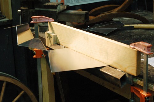
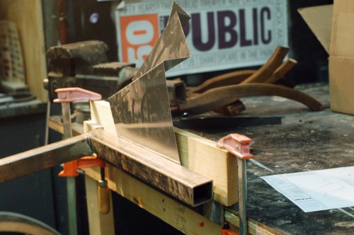
The next two photos show the brake making a fold. First, I had made a mark on a piece of scrap metal and lined it up in the brake to make a bend; this showed me where to line up the marks on the brake in order to place the fold where I needed it to go. Once I was confident with the workings of the brake, it was just a matter of making all 128 folds, one at a time.

Metal in the brake
Metal in the brake
Making the fold
Making the fold

I cut and attached MDF bases to the lights to give them a way to attach to the stage, and for the birdie lights to attach to them as well.

Attaching the bases
Attaching the bases

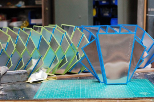
I then put masking tape along the borders of each panel. This quarter-inch area was to remain metallic while the rest was painted gloss black.

Taping the paintlines

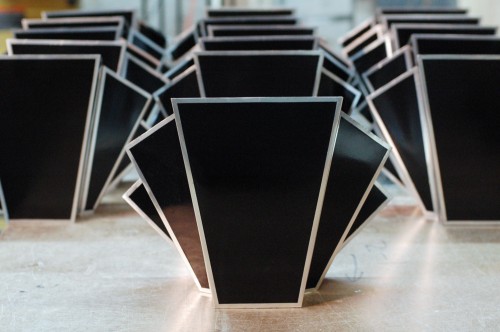
With the masking in place, all that was left to do was a couple of light coats of gloss black spray paint to build up a nice shiny and even surface.

16 footlights
16 footlights

Chandelier from Romeo and Juliet

As part of the new year, I’m going to be digging through my archives of props I’ve built in previous years. The first one is a chandelier I built for Romeo and Juliet. It was one of my first prop projects in graduate school, and the first prop I built which involved welding.

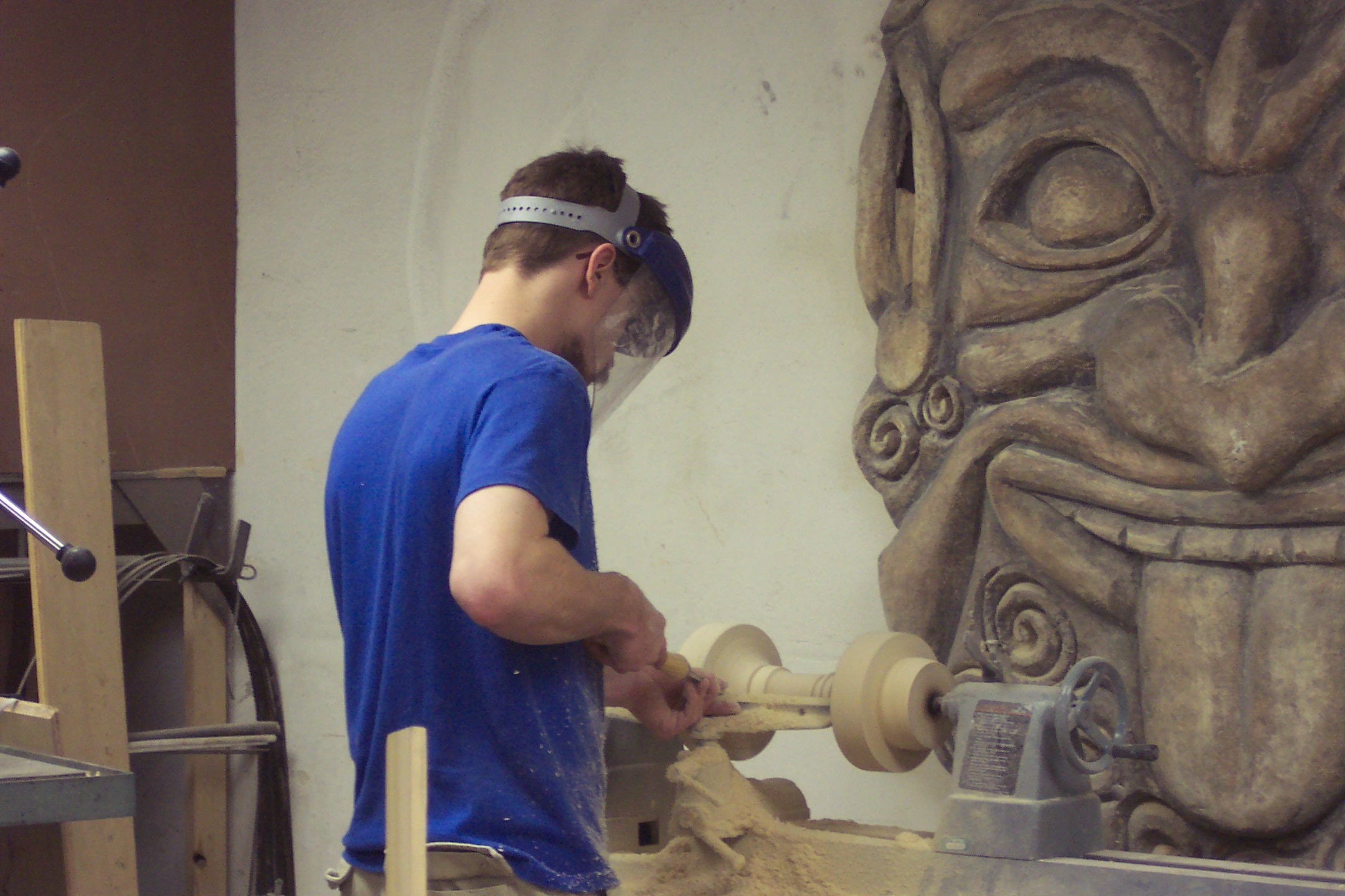
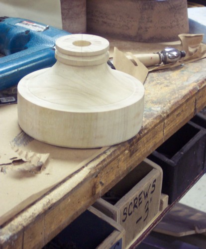
The first part I made was the body dish. I turned it on the lathe out of poplar. The outside needed to be a specific diameter, as we shall see shortly. I also drilled a hole through the center for the hanging hardware and wires to go through.

Turning the body dish
Body Dish
Body Dish

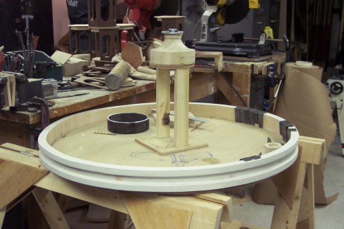
Next I cut a circle out of 3/4″ plywood to use as a template for the main ring. I made that out of several strips of what we call “wiggle wood”, which is a bendable plywood. I wrapped one layer around the circle, then glued another layer around the first one, with the seams offset so they would hold the circular shape. I added a thinner strip to the top and bottom to mimic molding.

The chandelier in the jig

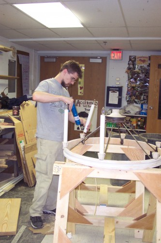
I left the chandelier in the jig and marked the center of the circle template. I then added a little stand with a smaller circle on top, also centered. I placed the body dish on top of that. This ensured that the body dish was centered within the ring, level, and at the correct height above the ring.

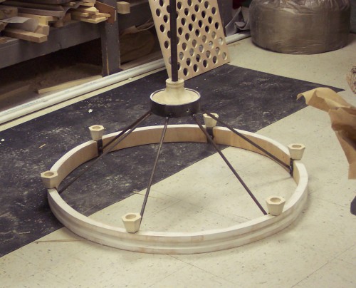
See that metal ring in the above picture? That is why I needed my body dish to be a specific diameter; the ring needs to sleeve on the outside of it. I cut the ring from a section of large pipe that was laying around. On the right side of the picture, you can see some metal brackets bunched together. These will be spread evenly around the wiggle wood ring and hold the cups for the candles. They will then have a metal rod welded to them, with the other end welded to the metal ring on the body dish.

The chandelier after the welding is done

Ta-da! I next ran wires out the bottom of the cups, along the rods, and up through the center. The only thing left to do was glue the electric candles into the cups, which you can only do with a bushy beard.

Gluing the candles in

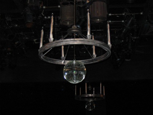
Actually, what I meant to say was that the only thing left to do was hang a big disco ball from the center, because every chandelier needs a disco ball.

Final Chandelier
Final Chandelier

Notice in the picture that I made more than one chandelier. The template and jig not only allowed me to get all the shapes and spacings correct, it also enabled me to duplicate the same prop without having to remeasure everything.

Steel Headboard for “In the Wake”

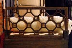
The next play to open here at the Public Theater is “In the Wake”, by Lisa Kron. One of the props they needed was a headboard. The design was based off of an existing style of headboard, but as the bed was a custom size to allow it to fit between the scenery, the headboard would also need to be a custom size. In addition, the bed moved to the middle of the stage where the headboard would be freestanding, and I was told the actresses would be leaning against it. For those reasons, a store-bought headboard would not fit the requirements. It had to be built, and it had to be built out of steel.

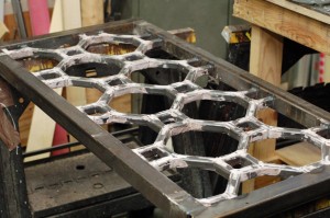
Since the design of the headboard was based around a repetitive pattern, the first thing I did was break it apart to make a cut list. I divided the pieces so the cut list would be as straight forward as possible, with as few angles as I could get away with. I managed to come up with a way where most of the pieces were straight cuts, and only a third of the pieces would need 45 degree angle cuts.

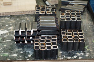
All of the pieces of steel

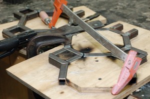
Before I could begin welding, I needed to create a jig. As you may already know, a jig is a device to maintain the spatial relationships between your materials, or between your tool and the materials. In this case, I wanted a jig that would allow me to lay my pieces of steel down in a consistent pattern while welding them together.

A jig for my headboard

I thought I was being clever by making only one section of the jig. The idea was that it would keep everything consistent. In hindsight, I should have made a jig of the entire piece. Then I could have dry-fit all the steel before welding it together, and adjusted the pieces individually to ensure they all fit. The way I did it, the piece as a whole ended up just slightly “off”, with the minute inconsistencies in my jig being amplified through repetition. Even someone as talented as me can still have learning lessons.

As you can see in the following photograph, I had to clamp it to make it fit even after adding just a few pieces.

Overcoming the problems with the jig

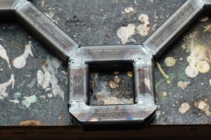
I decided to TIG weld this project. In theatre, the majority of welding we do is MIG welding steel. TIG welding is useful if you need to weld stainless steel, aluminum, brass, or if you need to weld two different kinds of metal together. In this case, I was TIG welding regular steel; even though it takes a lot longer, I could weld with little to no filler rod, which left me with very clean welds, and no spatter. I felt it was important for this piece since the cleanliness of the lines was an important part of the design. Plus, I wanted to brush up on my TIG welding skills.

A close up of the welds
A closeup of the welds

Even though I had TIG welded before, I still learned some new things about it. For one, the difference between using Argon and using an Argon/Carbon Dioxide mix is astounding. If you aren’t using pure Argon, you can literally watch impurities form on your tungsten electrode while you weld. Another tip I learned was that it is important to grind your electrode parallel to its direction, as opposed to in circles. TIG welding is so precise and exacting that little piddling tips like these really go a long way. Its actually a very Zen way to weld, if you have the time.

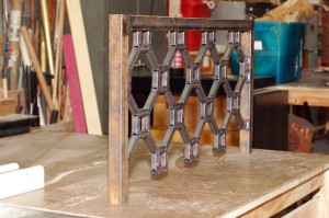
The mostly completed headboard

Once all the pieces were in place, my next step was to add Bondo to smooth over all the welds and fill all the holes. Bondo will cause nerve damage over time, so you must work with adequate ventilation and wear a respirator with cartridges that filter organic vapors. You should also wear gloves and sleeves to keep it off your skin, as it is a skin sensitizer as well. Remember that even after it hardens, you still need protective equipment while sanding it, as you release dust and fumes that can still harm you. With the proper safety precautions, Bondo is an incredibly versatile material for many projects.

Filled and sanded
Filled and sanded

After I sanded it all down, all that was left was to attach it to the bed, prime it, and paint it.

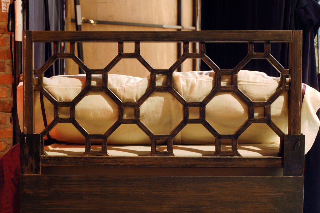
The finished headboard