Tag Archives: jig

Cannon Carriages

In previous posts, I showed off some foam cannon barrels I built and some giant champagne bottles I helped work on for the Santa Fe Opera. I also built the four carriages they rode around on.
Cutting the shape
Cutting the shape

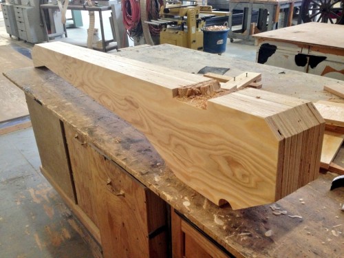
The main beams of the bases were cut out of plywood. I drew out a full-scale pattern for one of them and cut it out, then transferred it to all the pieces of plywood and cut those out to match. The bottom needed a square notch to hold the axle assembly, and it needed to be in the exact same location on all the pieces so the wheels would sit straight, so I attached all the pieces together and cut the notch out on all of them at once.
Assembling in the jig

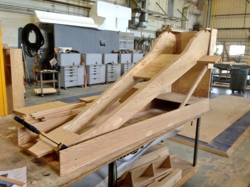
Next I built a jig to hold the beams. They sat at an angle and tapered out at the top. While in place, I measured and cut the cross pieces to fit exactly. This part took awhile to get perfectly correct, but once I had the pieces for one of them, I could just duplicate them for the other three carriages.
Attaching the facing

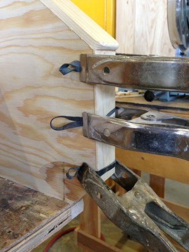
The carriages wanted to look like cast iron, so I faced all the edges with some strips of wood that were a little wider than the bases and rounded over on the ends. This gave it that look you might find on I-beams or similar pieces of metal. The photograph above shows a trick I read about that I wanted to try out: clamping a long strip of wood using rubber bands and spring clamps. It was not as effortless as I thought it would be, but it was a better clamping method than anything else I’ve used in the past.
Adding details
Adding details

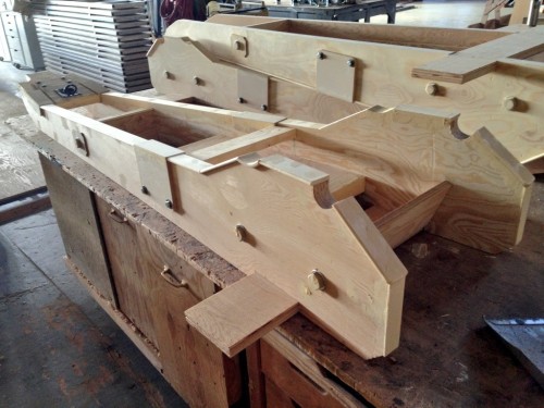
With the major structure in place, I began adding details, like bolt heads and plates. These were all applied pieces; I cut and shaped the larger bolt heads out of MDF, while the smaller bolt heads were just short lag bolts that I screwed in.
Positioning the axles

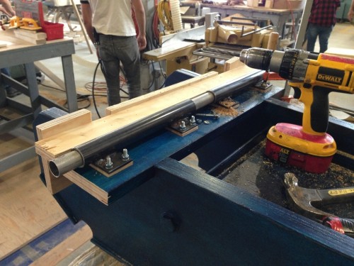
The wheels we used were bought from a place that makes wooden carriage wheels; I’ve made wheels in the past, but it’s very time-consuming, and hard to make them as strong as a legit wooden wheel. I attached a pipe to each of the wheels as an axle, and found a slightly larger pipe that could sleeve over them. I welded this larger pipe to some plates so I could bolt it to the carriage. In the photo above, you can see the axle pipe is in two sections. When building a carriage like this, you need the wheels to be able to spin independently of each other, because when you make turns, they spin at different speeds. The long aluminum pipe going through both larger pipes in the photograph was used to line them up with each other while attaching them.
Cannon for Duchess of Gérolstein‎

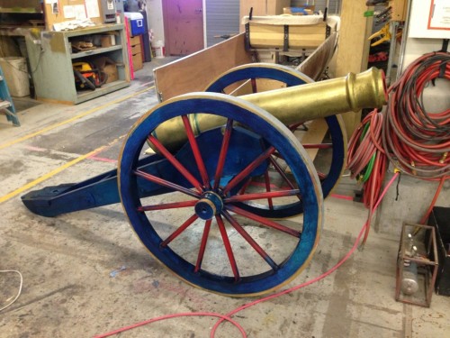
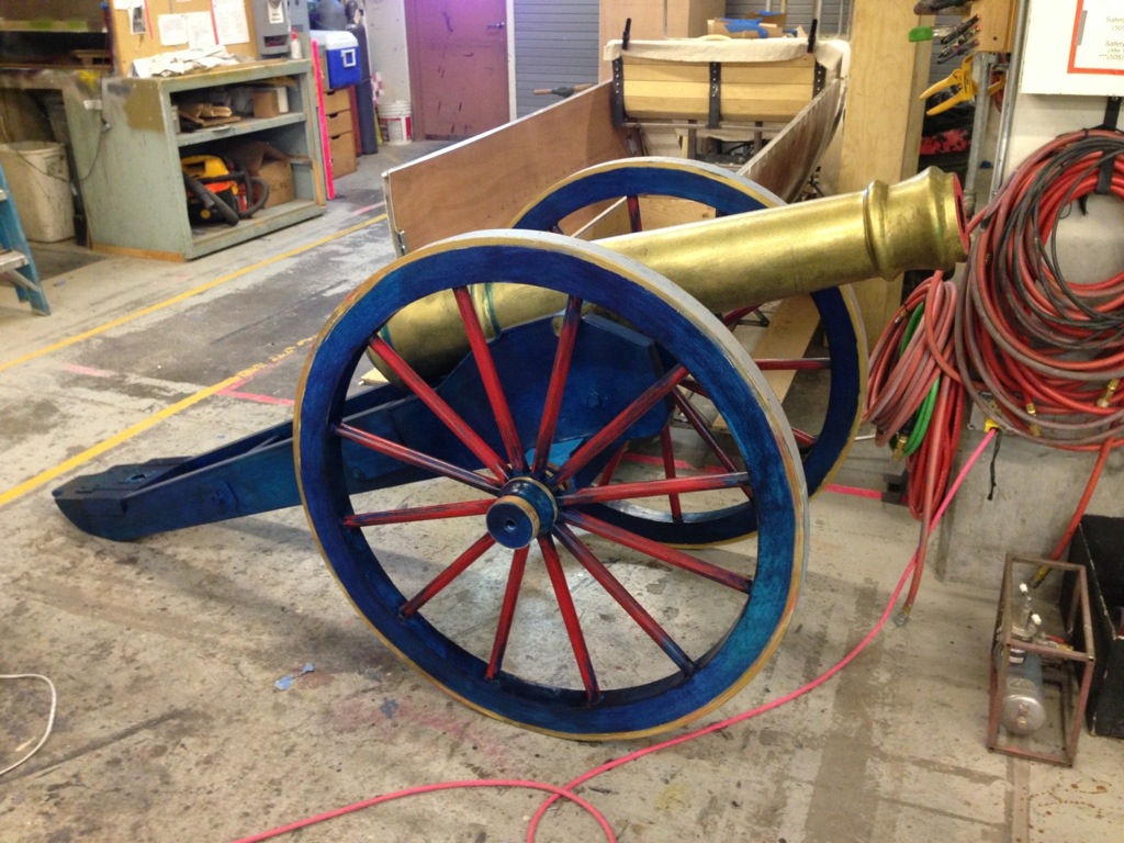
The whole thing got a pretty interesting paint treatment by the paint crew. Overall, it was a very fun project that saw a lot of stage time during the performance. It was also interesting to compare it to the previous cannon I have built, which could not be more different than this one both in appearance and in methods of construction.

Vacuum Formed Balustrades

One of the first projects I worked on when arriving in Santa Fe was actually for a scenic element. One of the shows has a number of decorative balustrades way upstage, and they wanted to vacuum form them. I was tasked with turning the wooden master.

Clamping the boards
Clamping the boards

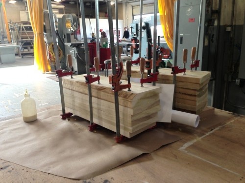
The first step was gluing up a number of poplar boards. This was going to be a fairly thick piece. I made two, so I could split them down the middle and give them four halves to vacuum form on a single sheet of plastic.

Turning the blank
Turning the blank

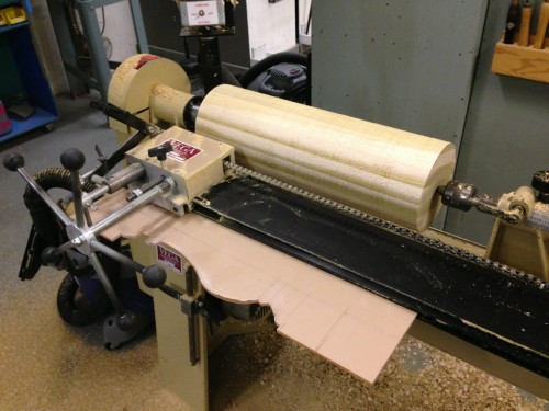
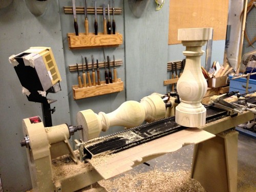
The lathe in our props shop has a duplicater set up. This allows you to cut out the profile of what you want to turn in a thin sheet of plexiglas, and the blade can follow that shape. You still need to finish it up by hand to make sharp corners and smooth it out, but it helps keep your shapes and sizes consistent across multiple pieces.

Completed balustrades

Above are the two balustrades, ready to go!

Cutting in half
Cutting in half

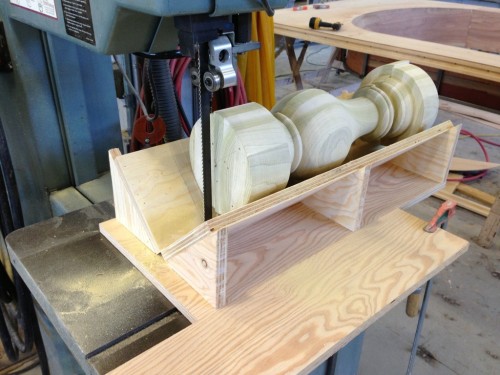
Next I had to split them directly in half. Luckily, we have a massive bandsaw, and I could build an oversized dowel-splitting jig to cut the whole baluster in half in one pass.

Mounting the wooden forms

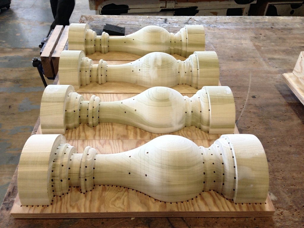
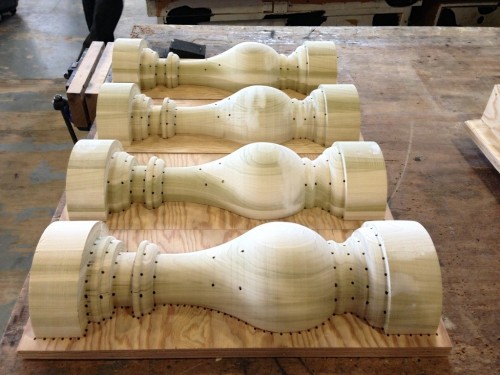
The next step included a new technique for me. I had to drill holes throughout the wooden mold for the vacuum to pull air through, paying particular attention to the undercuts. They also asked me to mount the molds on a sheet of plywood with a gap underneath, and drill holes all along the periphery. Since the vacuum form platen only has holes at regularly-spaced intervals, it would not suck the plastic tight against the bottom of the mold; this technique was like creating a custom platen to sit on top of the regular platen.

Vacuum formed copies

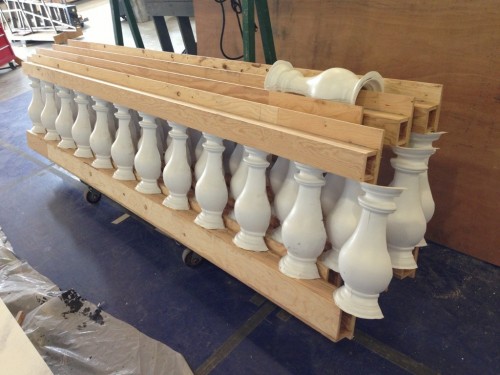
That was actually the end of my part. The scenery department took my molds and began running them through the vacuum former. I don’t have any pictures of that, but I do have a video of the machine in action. Above is a photo of the resulting pieces as they get mounted to the scenic piece.

Friday’s Rehearsal Notes

The Food Network gives some credit to the shows’ prop master (or design director). Wendy Waxman is responsible for decorating and accessorizing the sets of all the shows filmed at the Food Network’s studios at Chelsea Market.

Congressman Das Williams has introduced legislation to make flesh or proximity detection technology mandatory in all table saws sold in California after January 1, 2015. I have mixed feelings about this. I think safety is important, and I feel in a lot of situations, companies will put out unsafe products until forced otherwise; this is more true with chemicals and toxic substances. But this kind of feature on a table saw is expensive and unwieldy. The vast, vast majority of table saw accidents happen on untrained home hobbyists. [ref]Popular Woodworking analyzed the injury statistics for table saws put out by the CPSC last year.[/ref] This law would make trained users pay for a safety feature that’s more needed for untrained users. Not only that, but job site saws and contractor saws are far too small and light to utilize this technology; I’m only guessing, but I would imagine these kinds of saws are more likely to be used by home hobbyists. Why stop at the table saw? Why not legislate these features on band saws, planers and circular saws? Is it just because a table saw is statistically more dangerous? Because if we’re looking at statistics, a door causes just as many finger amputations per year as a table saw; why not require flesh detection technology on all doors? Anyway, it will be interesting to see how this plays out in the coming months.

Speaking of dangerous tools, AnnMarie Thomas makes the case to let kids use real tools to build things, and not those cheap toy versions. She mentions how an engineering professor asked his class of 35 first-year students whether anyone had ever used a drill press before, and not a single hand was raised. Looks like props people are single-handedly preserving manual-arts training in higher education. Maybe if kids were taught to use tools, we wouldn’t have so many table saw accidents (the majority of which are sustained by men in their 50s; age does not make one safer, only training does).

I’ve wanted something like this for awhile, but never actually sat down to plan one out. But this adjustable sanding jig for a disc sander looks like it’s the perfect design.

The Studio Creations website has a nice tutorial on vacuum forming plastic. Don’t have a vacuum forming table? No, problem, they have a tutorial on how to build one of those as well.

Chairs for Tea

Back in 2007 when I was working at the Santa Fe Opera, we were mounting a new opera called Tea: A Mirror of Soul. It had a heavy Asian influence, with scenes taking place both in Japan and in China. I was given a drawing of a chair, which they needed nine copies of.

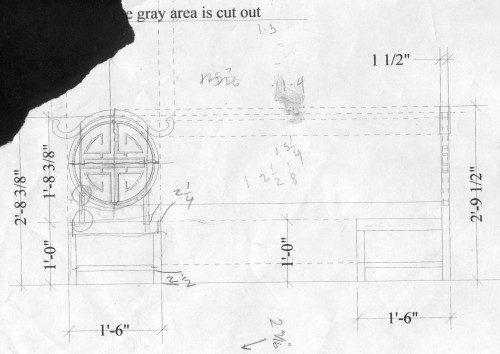
drafting of a prop chair

If you study the drawing, you’d notice a few things. First, it’s rather small. Normally, a chair is eighteen inches off the ground; this is only twelve. Second, the back stiles for the circular back are offset from the back legs (if you don’t know what a stile is, check out my “parts of a chair” diagram).  Wooden chairs usually have a single piece of wood running from top to bottom in the back for strength. Where the back meets the seat is the point where a lot of stress is placed on the chair, so relying on the strength of a joint rather than a solid length of wood is inviting trouble. Finally, you may notice that the back has pieces floating in the air. That’s always an engineering challenge.

attaching the back stiles

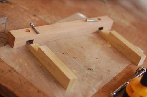
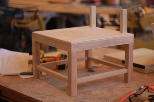
The seat of the chair was two and a quarter inches thick. I decided to skin the top with a piece of quarter-inch plywood and the bottom with eighth-inch lauan, so the interior frame had to be one and seven-eighths inches thick. That gave me a nice big chunk in the back to attach my back stiles to. I also added some bolts through the joint for extra reinforcement.

Bottom of the chair
Bottom of the chair

The rest of the joints were glued and doweled.

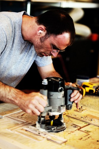
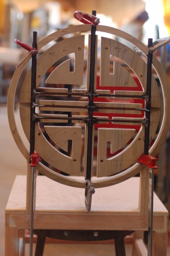
Next came the fun part: the back. We (the props master, master carpenter, and I) needed to figure out a way to make the back pieces appear to be floating. As I mentioned above, I was making nine of these chairs, so the process had to be repeatable as well. The master carpenter was also making a throne with this same cut-out design in it, so he began developing a jig so we could rout the design out of a solid piece of wood. We had discussed using plexiglass in the middle so the pieces would actually look like they were floating, but that would not be strong enough. Instead, we would hide a steel frame inside and have small pieces of steel connecting the pieces. Between the distance of the audience, the sightlines, and the smallness of the gaps, a few pieces of quarter-inch rod steel painted black would be as close to invisible as we could make it.

Dave making a routing jig

The photograph above shows David Levine, the master carpenter, working out the jig. Note that he’s not actually cutting yet, which is why his dust mask and goggles are off. It was a complicated, multi-piece jig with several steps involved, but the results were beautiful and consistent.

For the back ring, I sandwiched poplar boards on either side of a piece of quarter-inch plywood, with the grain of each side running perpendicularly to the other. In other words, I made a giant Oreo cookie out of poplar, with a creamy plywood center. The interior back pieces were cut out of a solid piece of poplar,  made by gluing several boards together. I put this in the jig and cut my design out.

steel reinforcement in the back

Before I had cut out the back pieces, I had routed the channels in where I would hide the steel rod. The channels were as deep as the diameter of the rod, so once they were in, the whole back could get a coat of Bondo and be sanded smooth, and no one would be the wiser. The steel rod continued sown into the stiles and up into the “horn” at the top so the whole back could be tied together with the same steel structure.

I cut the top horn piece out of a solid chunk of poplar, which I made by laminating two boards with their grains running in different directions.

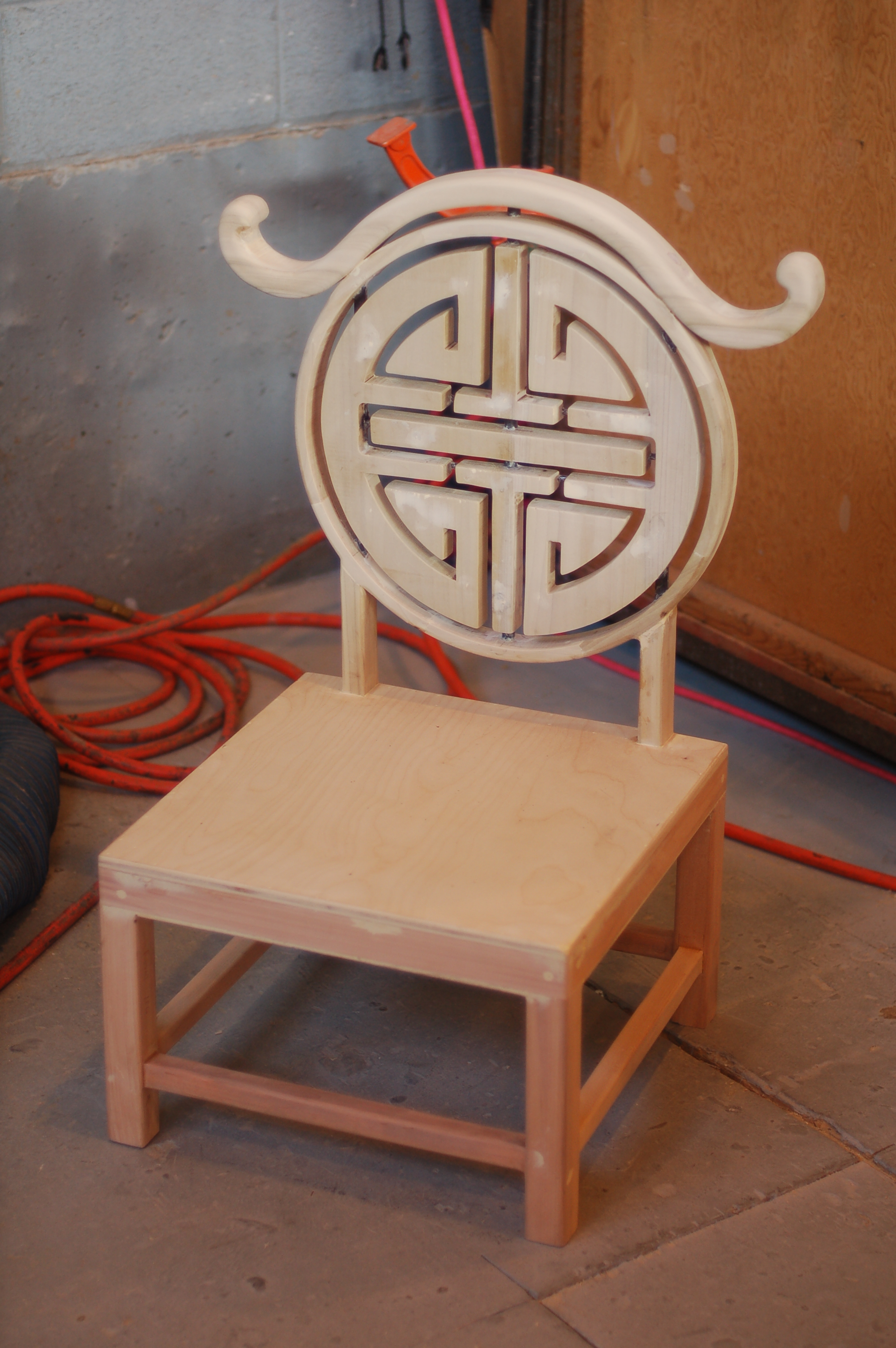
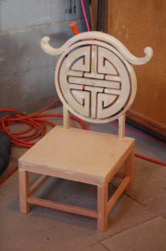
finished chair for Tea

Looking back, even as I write this article, I see a number of things I would do differently, or at least experiment with to see the results. As with any complicated prop, you learn a lot just by building it, but because you will never build the exact same prop again, it can be hard to assimilate that learning into your overall experience. As it turned out with this prop, I had only finished three of the nine chairs by the time they were cut from the show. It seems the stage was getting too cluttered, and the chairs were one of the more extraneous elements, so away they went.

That meant I got to keep two of the chairs, which let me test just how long my construction would actually hold up. The back on one of them did eventually break away from the seat, though not where I thought it would. I contemplated building more of a steel structure, but worried that the extra weight would either make it too heavy to carry, or even make it more likely to break; picture using a crowbar versus a stick of wood. The crowbar is extremely good at separating two pieces of wood from each other, where a stick of wood is just as likely to break itself before pulling the wood apart. Now look at a chair. The point where the back meets the seat is the focal point of a lever formed by somebody leaning back in the chair. If the stiles were metal (like a crowbar), it might tear the seat apart if you leaned back too hard.

But I digress and ruminate too much. Enjoy the pictures of the chair.

Sheet Metal Bending Brake

As I mentioned in my last post, I had to (or rather, wanted to) make a sheet metal bending brake for one of my latest projects. A brake is basically a tool (or jig) in which you can insert a piece of sheet metal, and then make a clean fold or bend in a straight line.

Front view of the brake

Again, I have to credit this post on Dave’s Sheet Metal Bending Brake for getting me up to speed on the best way to design a brake.

Side view of the brake

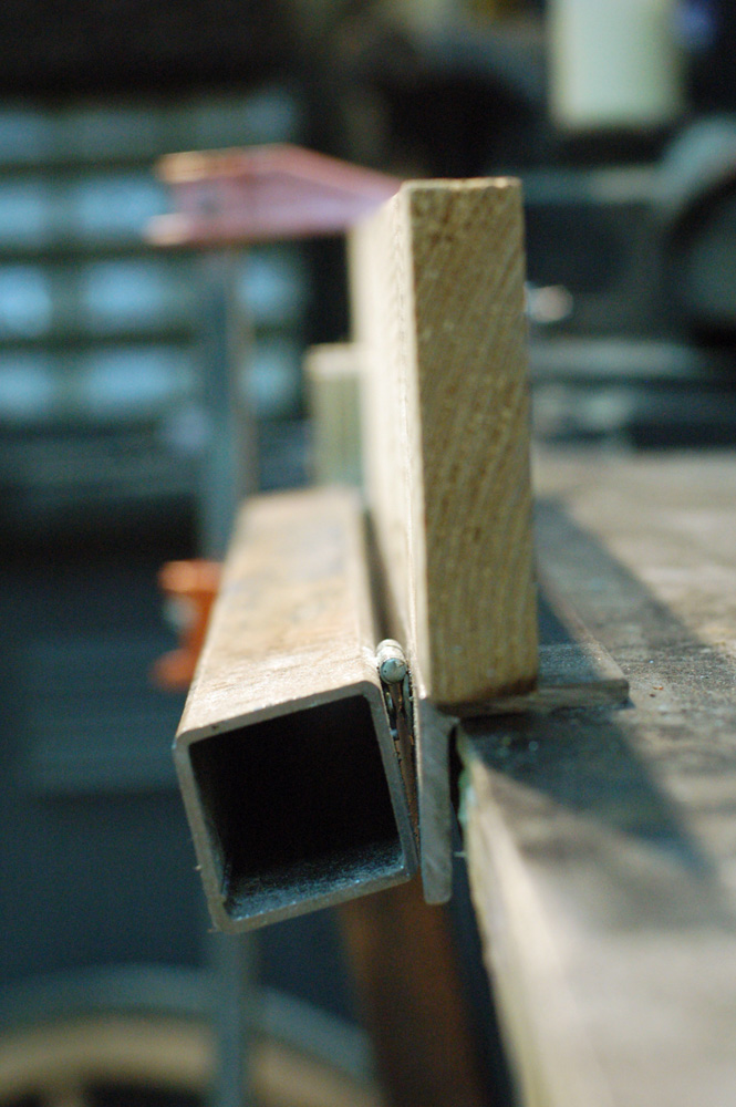
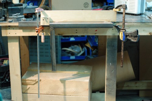
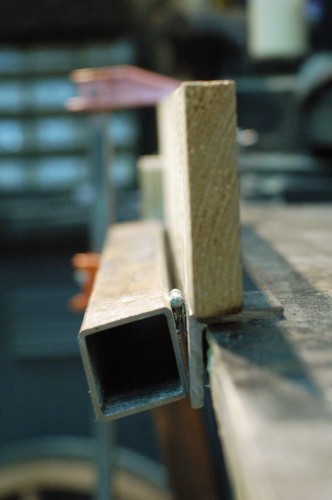
The piece of angle-iron is screwed to the worktable. The square tube is attached to the angle-iron by two small hinges, which are welded on. The tops of the bar stock, hinges and angle-iron are all in line with each other. Finally, I have a piece of wood which can be clamped down to the brake; the front face of the wood is lined up with the front face of the angle iron.

Sequence showing a fold being made

The metal is laid on the box tube and angle iron. The wood is clamped down. The fold will happen at the edge of the wood, so we mark the metal where we want the fold, and line that mark up with the edge of the wood. When you lift the handle, the metal bends with a nice sharp crease.

Here is a brief video of the brake in action making all the folds on one of the footlights.